Chronometric Micrometer
The Chronometric Micrometer is more widely used among amateur astronomer and is based on the apparent rotation of the celestial sphere. It consists essentially of a plastic protractor that, upright, remains fixed in the focouser; it freely rotates in a small tube, to which has been attached a disk of transparent acrylic the same diameter as eyepiece, with a radial dial that has been etched for reading of angles. Fixed to this is the actual eyepiece.
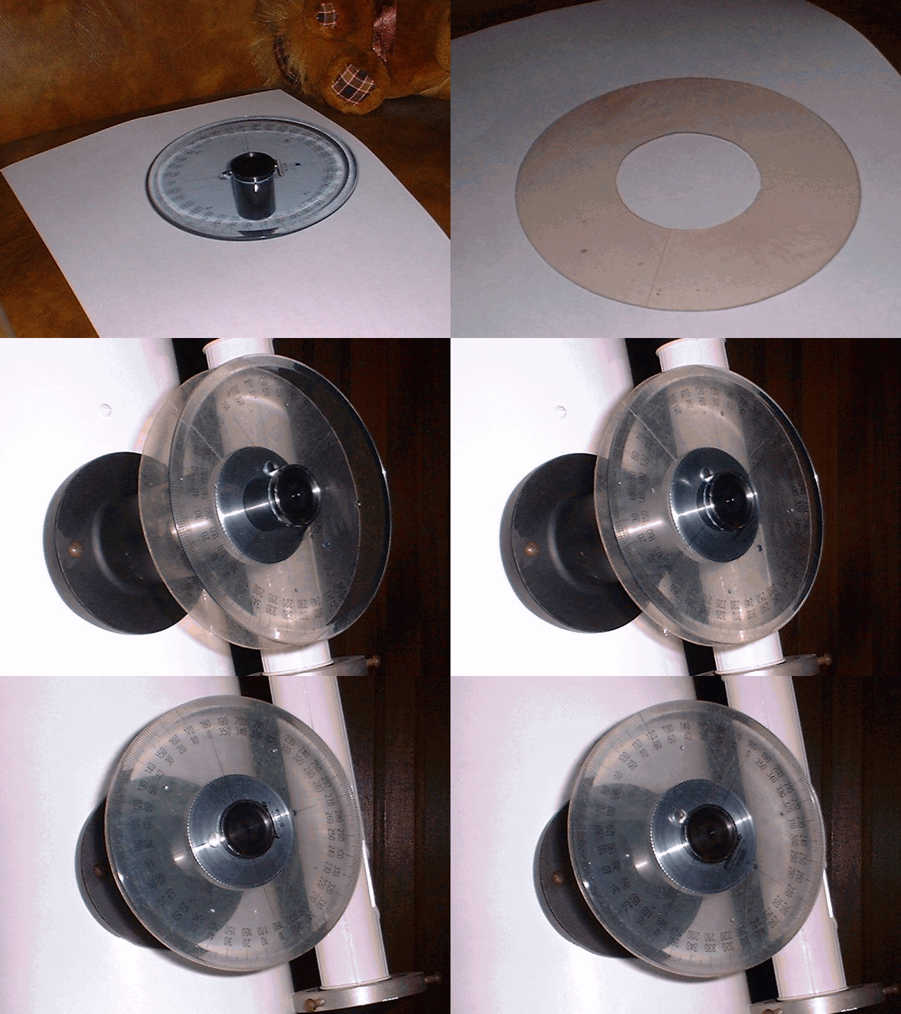
The first and most important step in this work depends on the location of the cardinal points in the field of the eyepiece. The location of these points should be of the highest possible accuracy.
- Moving the telescope toward the North (geographical), we see through the eyepiece that the image moves toward the South and the North enters in field of view.
- Moving the telescope toward the West (geographical), we see through the eyepiece that the image moves toward the East and the West enters the field of view; also, when the telescope´s drive is off, we will see that the image moves toward the West.
It is advisable to have an electronic RA drive system accurate enough to track a star for 30 minutes without too much image drift in the eyepiece. This instrumental difficulty is correctly called "position of station", that is to say that the telescope's RA axis should be accurately oriented so that it is exactly parallel to the axis of rotation of the Earth.
To determine the East-West direction, we move the star´s image through the East-West wire of the reticle, from one border of the eyepiece to the other (with the telescope´s drive motor off), simultaneously correcting the position (regarding the star´s displacement) by rotating the eyepiece, and seeing that the star goes through the center of the eyepiece and moves exactly parallel to the eyepiece´s East-West wire of reticle line.
The North point is located at -90º of the East line. In reality, it is very unlikely that the North will coincide with the dial at an angle of 0º on the protractor. Therefore, the angle of the protractor that indicates the north direction will be called X0, and this angle X0 will then be the origin of the PA measurements of our observations.
As before, it is recommended to carry out more than three measurements of the PA and AS and take the average in order to reduce errors. In this way, the observer´s experience, state of mind, night conditions, turbulence, and movements in the telescope will have less of an effect on the results.
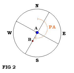
The PA is measured by centering the primary component in the reticle, as is shown in fig. 2, and then rotating the plastic disk, which also rotates the eyepiece, until both components are bisected by the proper wire of the reticle. The new angle is recorder (indicated by the plastic protractor) as X1. Therefore, the PA equals the difference between angles X0 and X1, as expressed by:
PA = ABS ( X0 – X1 ) ( equation 1 )
To obtain the value of the SA, we must take the time (t) in seconds that both components A & B take to cross, with the telescope´s drive off, the same wire of the reticle eyepiece, as is illustrated in Fig. 3 and Fig. 4.
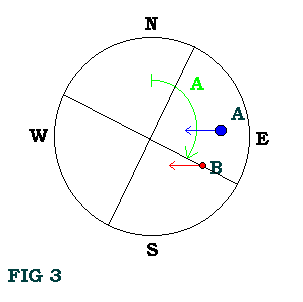
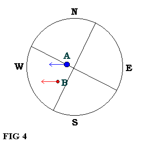
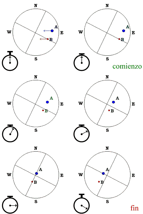
If the PA = 90° or PA = 270°, then the direction of the apparent motion of the two components will coincide, so the AS can obtained through the simple formula for uniform movement of the Sky, which is
AS = w * t * cos ( Dec ) ( equation 2 )
where w is the apparent angular velocity of the sky, approximately 15.04 "/second, (t) is the time the two components need to cross the wire of the reticle, and (Dec) is the declination of the system for the equinox at the time of observation. Through the cos(Dec), we establish the longitude of the arc that separates the two components, known as the angle (w)*(t).
However, it is improbable that the two components will be at a PA of 90º or 270º. Therefore, we must rotate the reticle wire to an arbitrary angle that we will call A (see Fig. 3), with the objective that both stars take the longest possible time (t) to cross the same wire of the reticle, which then decreases errors.
Table 1:
- If the PA is in the 1st or 3rd quadrant, the angle A must be greater than 90°.
- If the PA is in the 2nd or 4th quadrant, the angle A must be less than 90°.
We measure the angle A, as we did the PA, from the North to the East. When then obtain the AS using one of the following equations:
Table 2:
- If the PA is in the 1st quadrant:
AS = w * t * cos ( Dec ) * ( -cos (A) / sin ( A – PA ) ) ( equation 3 ) - If the PA is in the 2nd quadrant:
AS = w * t * cos ( Dec ) * (cos (A) / sin ( PA – A ) ) ( equation 4 ) - If the PA is in the 3rd quadrant:
AS = w * t * cos ( Dec ) * ( -cos (A) / sin ( PA – A ) ) ( equation 5 ) - If the PA is in the 4th quadrant:
AS = w * t * cos ( Dec ) * (cos (A) / sin ( A - PA ) ) ( equation 6 )
Example:
On the day of 16 July 1991 at 1:28 hs UT, we observe the double star Alpha Centauri. We first locate approximately the cardinal points in the reticle eyepiece´s field and then accurately determine the E-W direction. Using the method outlined above, we obtain the following angles:
PA1 = 215°30'
PA2 = 215°32'
PA3 = 215°28'
The average is, therefore, 215°30'. (215º.5). Following the procedure outlined in Table 1, rotate one of the wires of the reticle to an angle of A=100º (according Table 1), and then take three transit times. We obtain:
t1 = 13.45 seconds.
t2 = 14.14 seconds.
t3 = 14.23 seconds.
giving us an average of t=13.94 seconds. Using formula (5), because the PA is in the 3rd quadrant, and a Dec. value of -60°48'31.7" (-60º.8088), we obtain AS=19".67.
But it is worthy of to consider a subtle correction to our measurements, like Danjon A. recommends in his book "Astronomie Générale" (1952-1953, Paris, p. 42):
x = [ w * t * cos ( Dec ) ] * PI / 3600 / 180 ( equation 7 )
Sec( Dec ) = 1 / cos( Dec ) ( equation 8 )
DH = [x * Sec( Dec ) + {x3 * Sec3( Dec ) * ( (sin2( Dec ))/2 –1/3 ) } ] ( equation 9 )
t = [ DH ] * 180 * 3600 / PI / w ( timed time corrected ) ( equation 10 )
because, as we approach to the celestial poles, the stars don't follow straight lines but rather curves and then we take the time (t) that both stars take to cross this curve. Therefore, we should transform this time (t) to certain time (t-ideal) (situation in which the components would describe a straight line).
Admittedly, we must realize that measurements made with a filar micrometer and the CCD are generally more accurate than those made with the chronometric micrometer (transit method) or the angular micrometer.
